
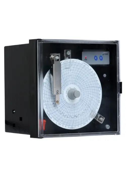
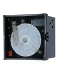
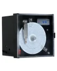
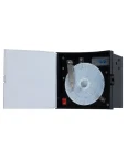
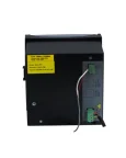

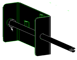
Inkless Recorder – CR4″
Inkless chart recorders from G-Tek is available in 4” and 6” chart size formats.
Part of G-Tek’s most popular series CR2010, they offer utmost reliability and versatility at an affordable price. Since the marking on the chart is through the pressurized needle, there is no need to worry about ink being exhausted or replacing the pen. Pressure sensitive papers are used instead of thermal papers to ensure that the marking is retained for longer period of time.
These 4” recorders are widely used in low-temperature equipment, blood banks, incubators and many more places. They come for RTD Pt-100 inputs, 4-20mA/ 0-1v process inputs. Standard chart speeds are 4Hr / 24Hr and 168Hr (7Day) per revolution.
These recorders are microcontroller based. Crystal controlled chart drive ensures the good chart speed accuracy. Stepper motors for both pen and chart drive ensures no lag and no backlash.
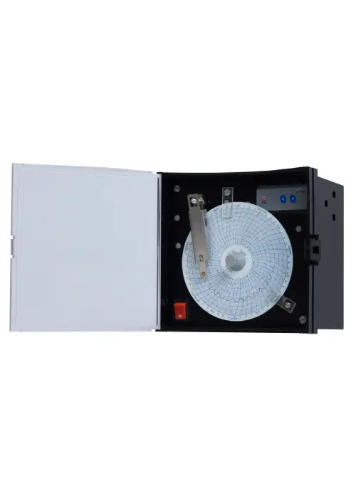
With a cutout of 138X138 mm and smallest depth, makes it very convenient to use. Transparent polycarbonate door makes the chart visible from distance. They come with a universal power supply as a standard feature. Other power supply inputs are also available.
Features
- 4” Chart Width.
- Inkless Chart Recorder
- Pressure Sensitive paper for long retention of data
- Single Analog Input channel
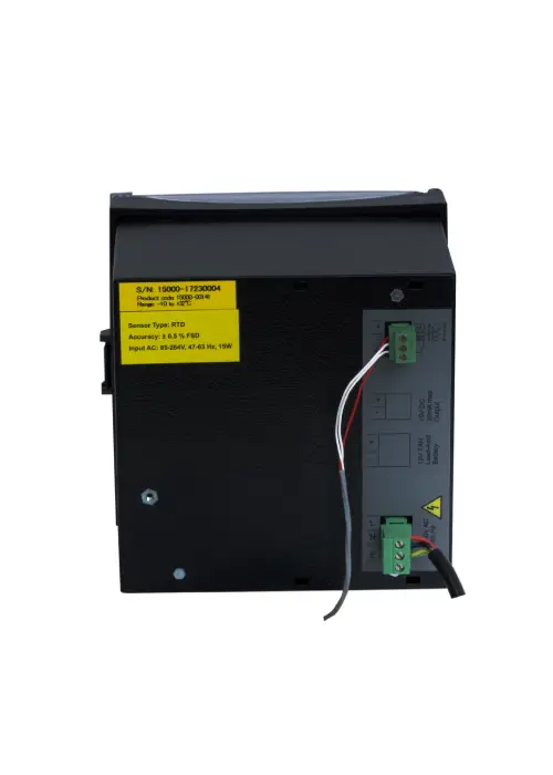
- Universal Power Supply 85-264 V AC, 47-63 Hz
- Other power supply inputs on request
- Battery Back up
- Direct Input Standard Pt-100 sensor.
- Process Input through 4-20mA / 0-20mA or 0-1V DC
- 7 Day for chart rotation
- Other chart rotation available on request
Specification
| Model No | CR2010 Series; 4″ recorder |
| Product Code* | 15×00 |
| Recording System | |
| Pens | |
| No. of Pens | 1, Pressurized Needle |
| Pen Marking | Continuous |
| Pen Response Time | <5Sec (Full Scale) |
| Pen Resolution | Stepper Motor Controlled better than 0.1% FSD |
| Overshoot | None |
| Chart | |
| Chart Speed | 7 days/rev; 24Hr/Rev and 4H/Rev |
| Chart Calibrated Radius | 1.3″ (approx. 34mm) |
| Chart Ranges | Standard (Refer Table 2) / Customized Please specify |
| Display, Operator Panels and Input | |
| Display Type | None |
| Status Indicator | Led |
| Panel Keys | Front panel KB consisting of 2 keys for programming and calibration |
| Analog Input | RTD PT-100 / 0-1 V / 4-20 mA / 0-20 mA (External shunt resistance of 50 Ohm 0.1%) |
| Sensor Type and Range | Refer to Table 1 |
| Scan Rate | Continuous 1 reading per second |
| Protection | |
| Input Impedance | |
| RTD/ Volt | > 20 MΩ |
| mA | 50Ω Shunt External |
| CMRR | >100 dB@ 50, 60 Hz at 3 Sample per Second |
| NMRR | >50 dB@ 50, 60 Hz at 3 Samples per Second |
| Maximum Common Mode Voltage | 5V AC |
| Isolation Channel – EARTH | 1.5KV 1 minute |
| Isolation Channel – Channel | NA |
| Input Protection | 30V AC/DC max |
| Termination | Non interchangeable, Removable Plugs |
| Transmitter Power Supply | Non Isolated 15V DC; 30mA max, un protected |
| Environmental | |
| Temperature | (Operation)5˚C to 45˚C |
| (Limiting) 0˚C to 50˚C | |
| (Storage)-20˚C to 60˚C | |
| Humidity | (Operation) 10 to 80 % RH Non Condensing |
| (Storage) 5 to 90 % RH Non Condensing | |
| Altitude | <2000 meter |
| Power Requirement | |
| Supply Voltage (Mains Operated) | 85-265VAC 47-63Hz |
| Battery backup | Yes |
| DC Adapter Operated | Yes |
| Power | 7W Max with Maximum Configuration |
| Fuse Type | None |
| Battery Backup | |
| Battery | 12V 7Ah External Lead Acid battery |
| Battery Charger | Yes |
| Battery Reverse Polarity | Protected |
| Minimum Back up | 24 Hrs. |
| Safety | |
| Safety | IEC 61010-1 |
| EMI-EMC | EN 61326-1 Class A |
| Pollution Degree | II |
| Installation Category | III |
| Vibration | 2g Peak (10 Hz-150Hz) |
| Shock | IEC61010-1 |
| IP Rating | IP50 (Door and Bezel only) |
| Overall Dimension | |
| Dimension L x W x D (mm) | 144x144x91 |
| Panel Cutout (mm) (L x W) | 138×138 |
| Bezel (mm) | 144×144 |
Table1: Sensor Type, Range, Accuracy and Max Error Specification
| Input Type | Valid Input Range | Resolution Chart | Accuracy | Linearization Error (Max) |
| PT-100(RTD) | -100 to +600˚C | 2% | +/- 0.5% FSD | ±0.7˚C Max |
| mA | 4-20 mA | 2% | +/- 0.5% FSD | ± 0.1% Max |
| mA | 0-20 mA | 2% | +/- 0.5% FSD | ± 0.1% Max |
| Volt | 0-1Volt | 2% | +/- 0.5% FSD | ± 0.1% Max |
Table 2 Standard Available Chart Ranges
| Sr. No. |
Range** |
Speed |
Size |
Part No. |
Part Description |
| 07 | -10 to +32 | 7 Days | 4” | 200618 | W4-1032PS |
| 08 | +32 to -10 | 7 Days | 4” | 303010 | W432-10PS |
| 20 | Other Please Specify | ||||
** First value in the chart is at the center of the Chart.
Specification listed are for each of the modules that can be fitted. Refer to the order code for the exact modules fitted in your system. Specifications for the modules that are not fitted, will not be applicable. Specifications are subject to change without notice.
Accessories
1. Chart Pack of 100
Standard Available Chart Ranges and Their Part No.:
| Sr. No. | Range** | Speed | Size | Part No. | Part Description |
| 7 | +32 to -10 | 7days/rev | 4” | 200618 | W434-10 PS# |
| 8 | -10 to +32 | 7days/rev | 4” | 303010 | W4-10+34 PS# |
| 20 | Other Please Specify |
** First value in the chart is at the center of the Chart.
# PS: Pressure Sensitive Chart
2. Panel Mount Clamps: (Available in Pair only)
Part No.: 210034
Downloads
FAQs
Inkless Recorder – CR4″
The pressurized needle marks pressure-sensitive paper, so you never need to refill ink — perfect for uninterrupted monitoring.
Yes, it supports RTD Pt-100, 4-20mA, 0-20mA, and 0-1V signals, making it versatile for any process.
Absolutely, charts can record up to 7 days per revolution, so you can leave it unattended confidently.
It includes a 12V 7Ah battery backup, ensuring continuous recording even if mains power goes out.
Yes, its compact 144×144 mm design and small cutout make installation easy, saving you space and effort.
Alternative Products
Explore other G-Tek options for this application.
Our Blogs
Engineering Ideas. Driving Innovation.

5 Reasons Why Every Stainless Steel Exporter Should Use a Data Logger
Stainless steel exporters face a silent threat during shipping: corrosion. Despite best efforts in packaging…
5 Essential Data Logger Features for Reliable Monitoring and Compliance
Why Choosing the Right Data Logger Matters In industries like pharmaceuticals, vaccine storage, and cold…
Follow These Steps When Buying a Temperature and Humidity Data Logger for Quality Assurance in Pharmaceuticals
Choosing the right temperature and humidity data logger is critical in pharmaceuticals, where accuracy and…